GTI-R US wrote:sorry to be a pain dave
but ive tried to study these maps/graphs and I ''if im honest'' haven't really got a clue whats what lol
can you explain it a little more please as its pointless me trying to make out im cleverer than I am

what do the blue, green and red segments represent?
what are the load figures?
and what are the figures representing in the coloured areas, is it a/f or ignition advance?
if I can get my head round the graph a little more then il have a better idea of what im doing
thanks and sorry for being a dimwit lol
Hi Bob,
No problem at all; happy to help!
GTI-R US wrote:
what do the blue, green and red segments represent?
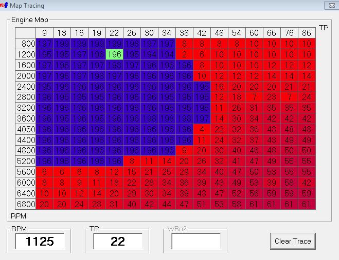
The graph is basically displayed on a sliding colour scale, where green equals small amounts of fuel, through to red which equals large amounts of fuel. The blue areas of the map basically show regions where the ECU is trying to force an A/F ratio of 14.7:1 by using the stock lambda sensor. These values are visible as those with a value greater than 192. If you don't care about which elements "chase" an A/F ratio of 14.7:1, then you can view their absolute fuel values by subtracting 192 off these numbers. Basically, (number+192) tells the ECU to use the lambda sensor to chase the ideal stoichiometric ratio. The first map shows the raw values (including those greater than 192 which show the RPM/load values where the engine chases an A/F of 14.7:1), while the second map shows the filtered fuel values (i.e. subtracting 192 from the large numbers to give the absolute fuel values):


You will see that low numbers (i.e. low amounts of fuel) are used at low RPM/load values, while high numbers (i.e. high amounts of fuel) are used at high RPM/load values.
GTI-R US wrote:
what are the load figures?
The actual load scale is calculated using the TP values, which correspond to the "Theoretical Pulsewidth". The TPS values typically refer to the "Throttle Position Sensor", which are not used in the calculation of the ECU load scale. In a nutshell, the ECU calculates the TP values using the equation:
Theoretical Pulsewidth (TP; basically the engine load) = MAF Lookup (essentially the airflow through the MAF) x Injection multiplier / RPM
This gives a value for the TP, which is then used to index the timing/fueling values as an input for the engine. You can imagine (from the equation above) that more airflow and less RPMs will give you a high TP value, and hence more "engine load". So now that the ECU can determine your engine load (from the above TP equation) and RPM values, it can find the cell on the fuel map that matches your current RPM/load values. Then, using the value printed in the fuel cell, you can easily calculate what the actual fueling pulsewidth will be:
Injection Pulsewidth = Fuel table [particular RPM, TP value] + Injector Latency + Various enrichments (which may correspond to different real-world corrections such as temperature)
It is important to remember that the load values (ie TP values) do not directly relate to vacuum/boost levels. However, these TP scales need to be updated depending on the boost you are running since more boost will result in higher loads on the engine. You can imagine that if you increase the boost, the airflow will increase, so the maximum TP value will also increase (since it's proportional to the MAF lookup). If you run huge boost and do not increase the TP scales, then the load value will max out early on when you come on to boost, resulting in the engine not being fed proper fuel/timing values for the high load levels you are running. Ideally you want the engines actual maximum load to correspond to the right-hand column of the fuel maps above. This will insure that the entire load range (idle to maximum boost) is contained within the fuel/timing maps.
GTI-R US wrote:
and what are the figures representing in the coloured areas, is it a/f or ignition advance?
The values printed in the fuel maps above are simple values that the ECU can turn into injector pulsewidth values using the above equation. If we use the above equation, we can calculate the injector pulsewidths (in milliseconds - ms) that the injectors will actually open for given a variety of RPM/load values:

I hope this helps a little. If not, let me know and I'll try to explain it better

Cheers,
Dave

 Home
Home


